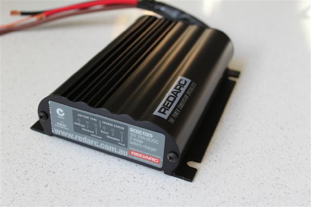
I recently installed a
Redarc BCDC1225 which is the latest DC-DC battery charger on the
market. This charger is an improvement on the BCDC1220 that
charges a vehicles auxiliary battery or more importantly a
remotely located battery in a camper trailer which is a long way
from the vehicles alternator. Over this distance the alternator
is only trying its best to charge the battery. The biggest
downfall in a situation like this is the voltage drop over the
distance involved, sometimes at around ten metres or more. An
alternator is known not to be the best thing to charge a battery
to full capacity, commonly only achieving 80%.
The auxiliary batteries in
4wd's or camper trailers are more often than not, deep cycle or
have a deep cycle capacity & used to power a large range of
power hungry accessories from 12volt fridges, tyre pumps to
lighting. A battery which is charged to 100% has more
useability, meaning a longer stay in camp without recharging.
The Redarc BCDC1225 not
only charges a battery from an alternator to 100% using the
inbuilt 3stage charger feature, but also from a solar panel
using MPPT solar charging, extracting the maximum available
power from your solar panel at any given time. This is a huge
advancement in solar charging & also a big plus for us camper
trailer owners. The BCDC1225 is also designed to isolate the
auxiliary battery from the main battery to avoid over discharge
of the main battery. The unit turns on above 13.2volts & off at
12.7volts.
what is
mppt?
MPPT stands for Maximum Power Point Tracking and relates to the
solar cell itself. Each solar cell has a point at which the
current (I) and voltage (V) output from the cell result in the
maximum power output of the cell. The principle is that if the
output from the cell can be regulated to the voltage and current
levels needed to achieve a power output at this point, then the
power generated by the solar cell will be used most efficiently.
MPPT ensures that you get the most power possible from your
solar panels during low light level conditions. All this
calculation and regulation results in the output from your solar
regulator providing the maximum current possible at the required
voltage at any given point. During low light level situations it
will compensate for the low light level and find the new point
at which the solar cell delivers its maximum power output.
what is 3stage charging?
stage one is also
know as boost mode & charges the battery at a constant amperage until the battery voltage
reaches around three quarters capacity.
stage two is also
known as absorption. This mode maintains the elevated voltage
from the bulk phase, but adjusts the amperage accordingly. As
the battery charge level approaches capacity, the current
approaches zero. Absorption voltage output from the BCDC1225 for an
AGM/Gel is 14.5volts, standard lead acid 14.9volts & a calcium
battery 15.3volts depending on the battery type as set by the
orange wire on the BCDC1225 charger at instillation.
stage three is also
known as float. After the battery is fully charged the voltage
is reduced to a lower level to reduce gassing and prolong
battery life. This is sometimes referred to as a maintenance or
trickle charge, since its main purpose is to keep an already
charged battery from discharging. Float voltage for an
AGM/Gel, standard lead acid & calcium battery are all the
same at 13.3volts.
getting
started
The best way to start a
major project is to draw up a diagram & a wiring job like this
is no exception. This way you can plan the length & size of each
cable, the terminals or any other hardware needed. I simply drew
my diagram in Microsoft Paint. If you do not have the necessary
computer skills there is nothing wrong with a sketch on paper.
Using different colours for positive, negative & line thickness
to represent different wires will also help you plan the job. It is a good idea to have the
diagram checked by a auto electrician or someone who knows their
12volt stuff. For the DIYer, Redarc also have technicians on
hand to answer your query via a user forum & a phone in centre.
Voltage drop is the number
one factor for many accessories not working to their full
capacity, especially 12volt fridges. A handy voltage drop
calculator can be found on the Redarc
handy hints page
of their website.
A big thanks to Simon
Gedge from Redarc & also Shane Adams at JTS, Jamie's Touring
Solutions, formally DSS, for checking the diagram I had drawn
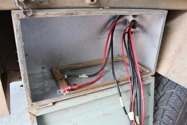
up. My own project was complicated by the fact the two 120amp
hour AGM batteries are in boxes on each side of the camper which
meant long cable runs protected by two 25mm flexible conduits. I
had the two batteries already set up & running, so this was more
of a rewire adding the BCDC1225 to the system.
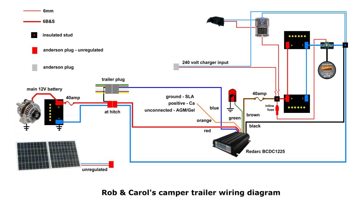
wiring
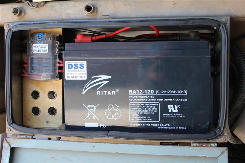
The two 120amp hour AGM or
absorbed glass mat batteries are wired in parallel, that is
positive to positive & negative to negative, making them in
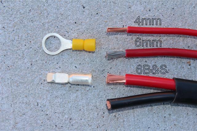
essence one big 12volt 240amp hour battery. I used 6B&S twin
core cable to join the batteries together as well as the
recommended heavier wiring off the charger.
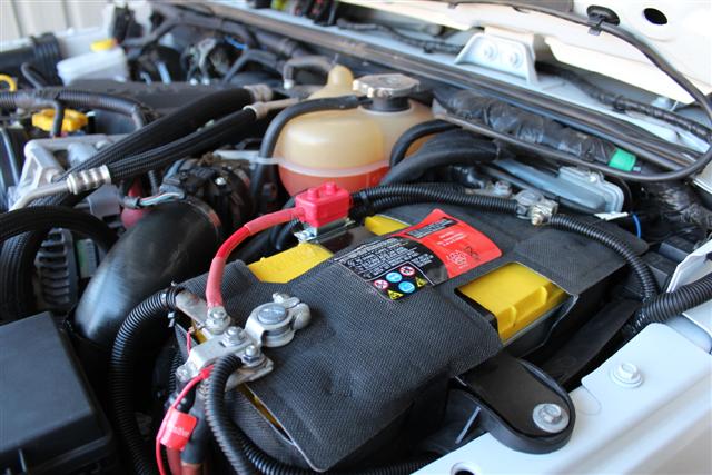
The two 120amp hour
batteries are also charged as one. The charger positive goes to
the positive on one battery & the charger negative goes to the
negative on the other battery. The brown wire from the charger
is only a short run to the positive battery terminal in the
battery box the charger is located in. The black wire from the
charger makes a longer run to the negative battery terminal in
the box on the other side of the camper.
The long nine metre run
from the vehicles battery to the charger is with 6B&S twin core
cable. All other wiring was run in 6mm such as to the fuse box,
the solar panel input & the 240volt charger input. I ran 5mm off
the fuse block to the accessories as I had a length of 5mm twin
core left over form the Redarc EBRH brake controller install I
did a couple of months ago. We had trialled a length of 5mm to
Carol's Cpap which worked a treat.
Discharge is the same, with
a positive off one battery & the negative off the other going to
the fuse block. The Baintech fuse block used has six terminal
blade fuses with its own positive & negative bus bar which makes
connecting the wires to outlet sockets a breeze. The cover can
also store two spare fuses.
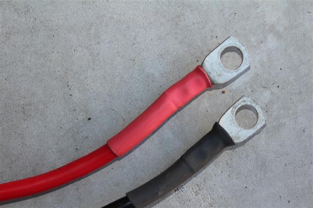
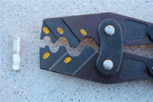
All uninsulated terminals
were crimped & shrinked wrapped. The connections off the charger
where crimped, soldered & shrink wrapped as per instructions. I
had bought an uninsulated terminal crimper off Ebay a while back
for $30 which did the job perfectly.
Auto accessory outlets do
not carry the type of wiring or the uninsulated crimp terminals
needed. After a run around to six different businesses in the one day I
only ended up with a couple of items. I bought most that was
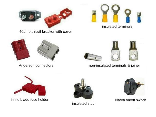
required off Ebay. The ten metres of 6B&S twin core cable was
$89 & ten genuine 50amp Anderson connectors for $30. I also
needed four red 50amp Anderson plugs at $20.
You need to be careful
when buying 50amp Anderson connectors as some ads read Anderson
'type' connectors which imply they are not genuine. The crimp
terminals on cheap copies rust, therefore do not make good
contact over time. The contacts of genuine Anderson connectors
are self cleaning as you push them together, making for
excellent contact with each use. There is also an Anderson logo
on each genuine plug.
charger
input configuration
The wiring diagram that
comes with the charger install booklet shows three choices for
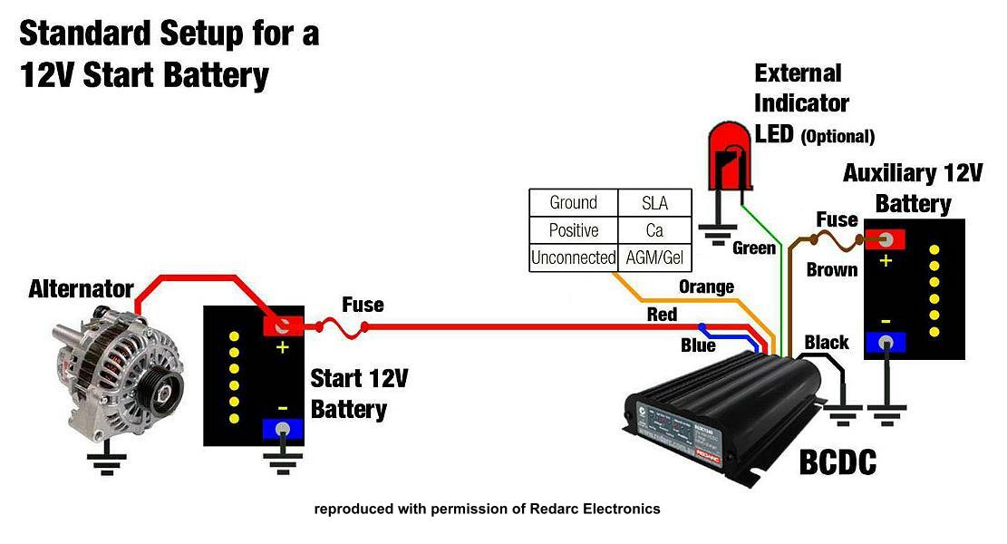
which the charger will operate depending on how the blue wire is
configured -
* the blue wire is
connected to the ignition for alternator input
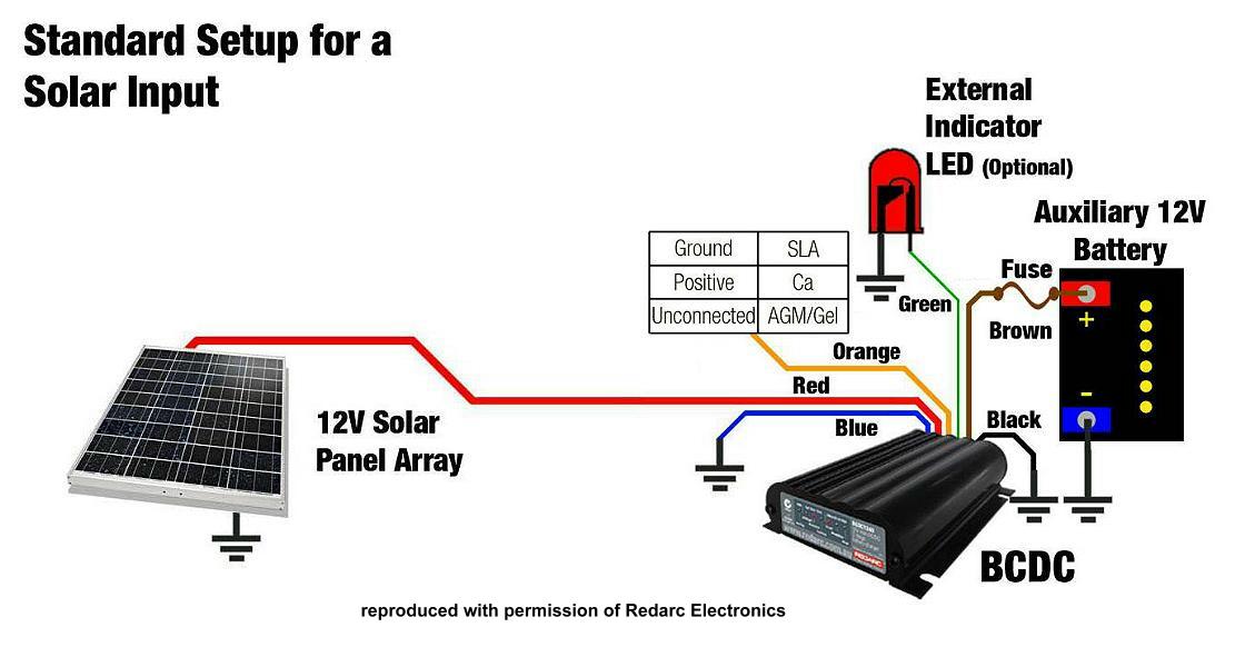
* the blue wire is grounded for solar input
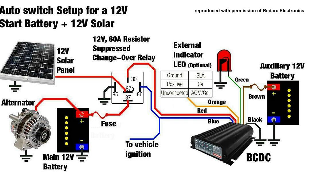
* or if you want an automatic connection for solar & alternator
use you can use Redarc's RK1260 relay which is a setup perfect
for a van with the panel permanently on the roof. When you turn
the tow vehicles engine off the solar panel will automatically
cut in.
solar &
alternator input
The Redarc BCDC1225
requires unregulated solar input from the panel for the MPPT
solar regulator side of the charger to work. Luckily there was
enough room in the box on the back of the Kyocera 130watt
folding panel we bought from Jamie at Dynamic Solar Solutions,
now known as Jamie's Touring Solutions. Other than that I would
have had to take the regulator out & put it in a jiffy box to
use when needed. Something else to carry & store. I picked up
the wires on the back of the panel before they went through the
Plasmatronics PL1210 regulator & brought them out to a red 50amp
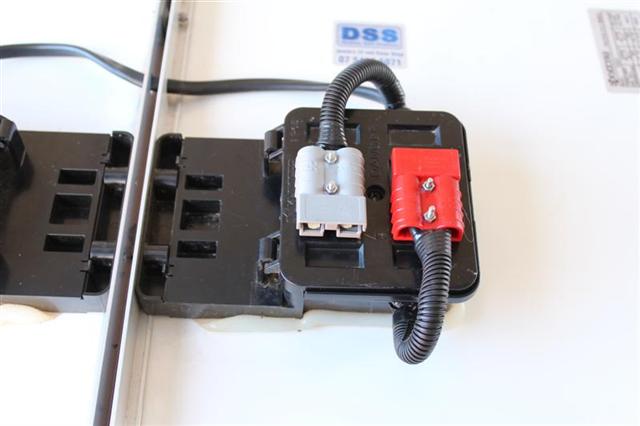
Anderson connector. I used a red Anderson to signify the output
from the solar panel is hot ie unregulated.
A grey 50amp
Anderson connector on the solar panel signifies the output is
regulated which I can use to charge the vehicles battery or any
other 12volt battery for that matter. The two Anderson
connectors were secured to the box on the rear of the solar
panel with small nuts & bolts. Loctite was used on the threads &
a blob of silastic over the bolt heads inside to make sure the
bolts didn't come loose, fall in & short something out.
my input
solution
In our situation the
130watt portable panel is carried on the campers bed & setup
when camped which meant none of the above scenarios where right
in how we would use the charger. With the help of Redarc's Simon
Gedge & the Redarc tech guys, they came up with a very simple
solution to our situation.
I have run the blue wire from the BCDC1225 through the
black unused reverse pin on the trailer plug & joined it to the
positive lead from the alternator at the Anderson connector on
the back of the vehicle.
When the vehicle is running the blue wire tells the charger
the alternator is feeding & the charger acts as a 3stage
charger.
When we are camped the
trailers red Anderson at the hitch is disconnect from the
vehicle & plugged into the unregulated solar panel at the A-frame.
The campers batteries are then charged with the inbuilt BCDC1225 MPPT solar regulator.
There is also a grey 50amp
Anderson on the side of the battery box for the 240volt 3stage
charger to connect to the two batteries. A red Anderson will not connect to
a grey Anderson so I cannot accidently make a wrong connection.
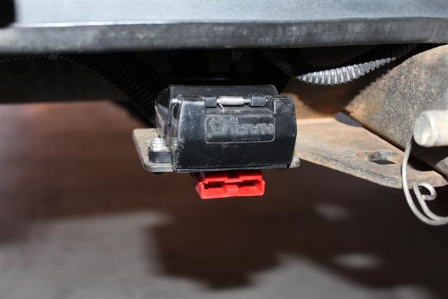
vehicle
wiring
I ran a 6B&S twin core
cable from the vehicle's battery via a 40amp circuit breaker
with protective cover to a red 50amp Anderson connector on the
towbar next to the trailer plug. This gives plenty of feed to
the charger without excessive voltage drop over a nine metre run to the
charger. Sometimes 6mm auto cable is mistakenly used instead of
6B&S which is not large enough to carry the voltage required.
battery
type selection
The BCDC1225 will charge a
battery depending on its type according to the way you wire the
orange wire during installation.
* standard lead acid - grounded
* calcium - connected to input positive
* AGM or Gel - not connected
display
panel
There are two displays on
the front of the charger that explains what is happening. The
first shows the battery type selected during installation.
The other shows the charge
status. An LED will flash whether the charger is in boost,
absorption or float mode. The longer the flash, the more current
the charger is putting out. If the LED in on solid, then the
unit is supplying a full 25amps to the battery.
In standby mode the battery
type LED will blink at approximately once per second & the
charge status LED will be off.
external
led indicator
A green wire on the unit
is provided that can be connected to an external LED, say in the vehicles dash,
that will let you know what the battery is doing. If the LED is
on, it means the battery is charging, if the LED is off, the
BCDC1225 is off.
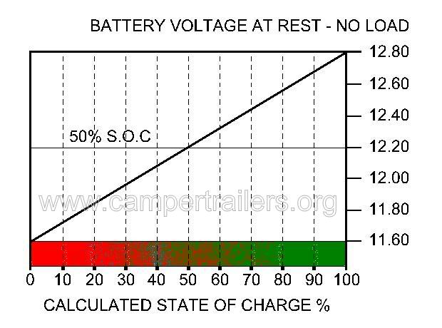
voltmeter
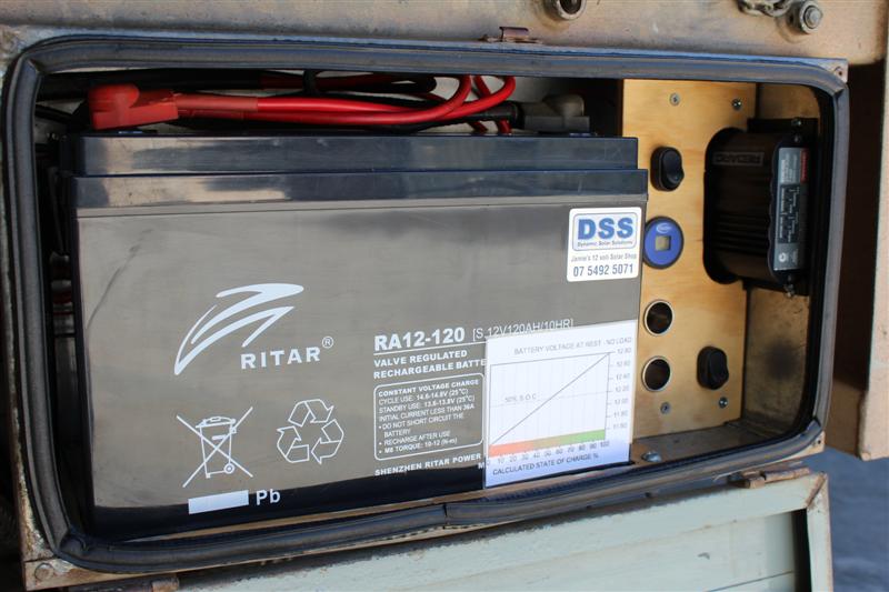
I wired in a voltmeter via
a switch to the positive on one battery & the negative on the
other showing the state of charge at rest which is best achieved
by allowing the battery to sit overnight. I find it better to
understand the battery capacity by using a simple chart to show
a percentage. For best battery life & optimum performance it is
recommended that you only discharge your battery to around 50%
capacity.