|
12volt
power
for our
cub supermatic
Arguably one of the most written about and discussed topics relating
to camper trailers. Here is the solution which I came up with to
satisfy my ‘power on the go’ needs, as well as a few of my creative
ones, after purchasing a new Cub Supamatic Escape Off Road Camper in
May of 2010.
It would be adaptable to other types of campers with some
extra thought and planning and I will apologise in advance if there
is too much information provided, but as with all articles, I have
no idea of the knowledge or ability of any readers. If in doubt ask
an auto electrician or someone who has done it before. It does cater
for the ‘first timer’ so those that have been down this path before
will no doubt ‘skim’.
My personal experience with
magazine articles on this subject, whilst coming up with great ideas
and pictures, they do tend to leave you scratching your head at the
end of the article as to what has actually been done in between some
steps to achieve the end product, my aim is that does not happen
here.
background
The Cub is our second camper trailer. In late
2003 we purchased a 2nd hand Adventure which had been returned to
the manufacturer in Adelaide for reselling. This was the trailer
that my wife Francine and I and our two children, Jessica (14) and
Andrew (12), were to spend three months travelling through South and
Western Australia and the Northern Territory in. We did pretty well
every iconic destination possible, I won’t list them all here and it
was the trip of a lifetime. There are not many travel shows
highlighting these areas that I can’t watch and say “I’ve been
there” and settle back into the lounge with a contented smile and
start reminiscing, and planning again !
The Adventure suited us as it was the early model with two
double beds (closer the ¾ beds actually) and plenty of storage. It
also came ‘12volt-less’ and was my first attempt at a 12volt
electrical fit out.
After the trip we kept the Adventure for another twelve
months or so and as the kids got older and showed less interest in
holidaying with us we sold it as the bed setup was not ideal for
two. I had added home made boat/wood racks and done the electrical
fit out, including a 90 amp hour GEL battery and got what I paid for
it after owning it for nearly two years. I would call that a good
investment.
When ‘the itch’ couldn't be satisfied by no other means (and
doing a delivery run on a Cavalier for my brother-in-law to Victoria
over a week didn’t help either) and after doing much research and
working within budgetary constrains, we headed off to Cub in Sydney
to look a demo trailer, which sold before we got there, we ended up
with a great deal and four months build time to save up some more
‘hard earned’ and ended up with a new camper for the same price
instead.
The Escape model (read ‘poverty pack’) came with some basic
wiring i.e. 1 x internal and 1 x external 12volt ‘merit’ type socket
wired through the trailer plug to run off the starter/aux battery of
the tow vehicle, along with a 15 amp 240volt inlet on the off side,
1 x double GPO and a C/B RCD combo inside and 1 x ext GPO on the
near side. No battery or charging or lighting is provided. Of course
these things can be added as options, but even Cub will admit that
whilst their trailers are good value for money, their options come
with a premium price tag.
tow
vehicle set up
I still own the same tow vehicle used for the last big jaunt,
a ’98 Holden Jackaroo S TD manual which I had purchased specifically
for the trip 2nd hand in 2005. It already had a dual battery system
fitted which consisted of a manually operated charging solenoid, a
home made battery cradle which was just large enough for a 50 amp
hour battery and a rear mounted cigarette socket and dash switch. A
basic set up which worked fine, so long as you remembered to push
the ‘under dash’ mounted button to connect the auxilary battery to
the starter battery to charge it up ! This didn’t last long and the
solenoid was replaced with a 90 amp Matson voltage sensing relay.
These are a fully sealed unit which isolate the main and auxilary
batteries, sense when the main is fully charged and then
automatically sends power to charge the auxilary battery. I also ran
a pair 6 B&S gauge cables from the auxilary battery through the
firewall and via the interior of the vehicle to the tow bar and
mounted a 50 amp Anderson type socket. I still have the same set up
six years later and has never failed. Packing the back of the
Anderson plug, where the cables enter, with silicone to keep the
dust and water out is not a bad idea either.
There are better ways to charge an auxilary battery these
days, such as a multi stage C Tek, Redarc, ABR Sidewinder or
Projecta, to name a few, 12v/12v charger, these generally cost more
but will probably make your auxilary battery last a lot longer. For
under bonnet applications the Redarc is probably the pick due to its
compact size as well as many other dual battery charging systems on
the market from many manufacturers. Redarc makes a cracker but you
will need deep pockets! My next pick would be one of the Piranha
units.
what I
wanted to achieve
My goal was to be able to recharge batteries and/or provide
power, regardless of the location, the time of day or the weather
conditions and also to make use of the equipment that I had
accumulated over the years. I also wanted to be able to monitor the
condition of the batteries and how much load was being placed upon
them. Sound familiar ?
what I
already had
Apart from the modifications to the vehicle I also had a 80
watt solar panel fitted with a Projecta regulator and a Honda Eu10i
inverter genset. I wanted to incorporate both of these into the
project. Both are not required, but at least one would certainly
make life easier when it comes to recharging batteries for a long
stay. If I did not already own the genset I would have at least
another solar panel of the same size or bigger.
my first
attempt
As previously mentioned the Adventure had no 12volt electrics
or lights either.
My first go at wiring a trailer was attempted with minimal
research and doing it as cheap as possible. It consisted of, from
the tow hitch, a 50 amp Anderson plug, 2 x 6B&S cables to a 2nd hand
90 amp hour sealed GEL battery and a series of cigarette sockets
scattered around the trailer and that was about it. Lighting was
provided by a couple of fluro camping lights from ARB. Coupled with
the 50 amp hour battery in the Jackaroo this gave me a total of 140
amp hours of power – or so I thought at the time. I was running an
80 litre Waeco fridge freezer as well to cater for the four of us
over an extended period of time. This fridge served us well and has
never missed a beat since we bought it but, when using it as a
freezer, it does like it’s quota of electrickery !
What I didn’t realise, due to lack of research, was that
because I had the 50 amp hour battery wired parallel with the 90 amp
hour and the 50 was receiving it’s charge first from the VSR, the 90
was never getting its full charge. Adding to the problem was the
voltage drop over the 12 metres or so of cable that ran between the
two batteries from the engine bay to the back of the trailer. My
true amp hour capacity may have been less than 100 amp hours. During
our time north of Broome, in the Kimberly and the Pilbara, I was
lucky to get two days out of the batteries even with the solar panel
attached. The mistake I made with the solar panel was using wire
that was barley heavier than automotive speaker wire, so I was
electrically ‘strangling’ it as well. Another really annoying
problem that occurred was after one day of ‘sitting still’ I had
great difficulty getting the fluro lights to ‘fire’ because of the
voltage drop in the batteries. I had to start the car and get the
auxiliary batteries into a state of charging to increase the voltage
and get the lights to come on. So you can see that not much had gone
right in this project.
the cub
project
|
Parts list |
Supplier |
| Anderson plugs (10 pack)
|
ABR Sidewinder Ebay Shop (Derek
Bester) |
| Anderson plug dust boot |
ABR Sidewinder Ebay Shop (Derek
Bester) |
| 6 B&S cable x 6 metres black &
red |
ABR Sidewinder website |
| heat shrink to suit
|
ABR Sidewinder website |
| cable lugs to suit |
ABR Sidewinder website |
| battery switch |
ABR Sidewinder website |
| large electrical box |
ABR Sidewinder website |
| 1.5 metres 16mm split flex
conduit |
auto accessory store |
| 50 amp C/B “ “ “ |
auto accessory store |
| 12volt switches with LED -
Narva 62059 BL |
auto accessory store |
| spade connectors |
auto accessory store |
| 15 amp wire red & black |
auto accessory store |
| 50 amp wire red & black |
auto accessory store |
| fuse block - Narva 54430 – 35.
Depending on needs. |
auto accessory store |
| 20 amp Ctek 12v/12v battery
charger - $345 inc p&h |
4WD Extreme Ebay store |
| 25 amp Ctek 240 v/12v battery
charger - $385inc p&h. This item optional. This was the
biggest charger my genset would handle.) |
4WD Extreme Ebay store |
| battery - min 80 amp\hr) Shop
around for this one. Must be sealed so no gasses when
charging. I chose AGM type. |
Battery World |
| Matson battery tray - coated
steel |
Battery World |
| battery hold down - Matson |
Battery World |
| digital volt meter |
Ebay various |
| digital amp meter |
Ebay various |
| merit & cigarette sockets
|
Ebay various |
where's it all
going
As with any project like this remember; check everything at
least three times; measure at least twice; cut or drill just once.
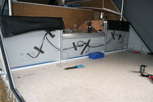
Inside the trailer decide where you will fit the battery and
charger. I chose to put them under the bed as there was a space
between the wheel arch and the rear bed bulkhead on the near side of
the trailer (same side as the cable run through the draw bar) which
was a perfect fit for the battery and will allow for future upsizing
if needed and it was an easy space to work in. This also kept the
charger nice and close to the battery and for close mounting of the
control box on the opposite side of the bulkhead.
existing
wiring modification
There is a piece of panelling at the back of this space which
needs to come off to get to the wiring behind it so remove it now,
there is also one directly opposite on the other wall about the same
size, it needs to come off as well to get to the wiring behind it.
Behind this panel (on the drivers side) you will find a black wire
(this is the 12volt supply from the trailer plug that we no longer
need) and two white wires (12volt supply to the internal and
external merit sockets) all terminated together. Remove the
terminator and separate the three wires. Rejoin the two white wires
and refit the terminator and cut the black wire off flush and just
leave it, you can wrap the end in electrical tape if you wish.
On the opposite side behind
where the battery will go, you will find two white wires terminated
together. This is the feed to the out side merit socket and the
12volt supply from the opposite side that you just changed. Remove
the terminator and add length of 10 amp red wire, enough to reach
the control box, and refit the terminator. This red wire will become
the new fused 12volt supply to the two merit sockets. The panel can
be refitted now if you wish, I didn’t bother because the battery
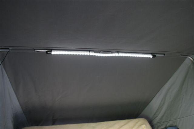
will fill this area up later. If you plan to fit and annexe light on
the side of the trailer fit it now so you can run the wires to the
control box before the battery goes into place.
The only variable here may be the colour of the white wires;
I don’t know if Cub uses the same colours on each trailer, just have
a look at the rear of each merit sockets’ centre connection to
check. Each socket will also have a yellow/green earth wire attached
as well, don’t alter them.
The 6 B&S cables will come up through the floor right next to
the bulkhead so fit the battery tray very close to the wheel arch
wall. The charger was mounted on the inside of the bed bulkhead,
very near to the battery and the control box on the outside of the
bulkhead. This kept the cable runs to a minimum and avoided voltage
drop, even if only a little.
fitting
the charging cables
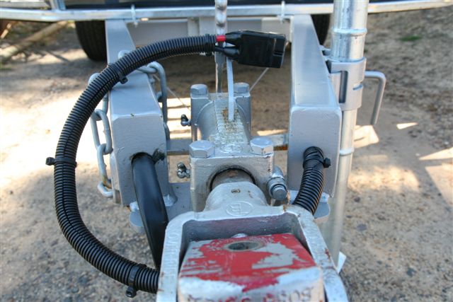
Starting from the tow hitch. Fit a 50 amp Anderson plug to
the end of a pair of 6 B&S cables about 6 metre long each. I also
fitted a dust cover over the back of the Anderson plug. Both these,
and many other items, came from the ABR Sidewinder’s Ebay shop. A
ten pack of Anderson plugs cost me $30 + $5 p&h, that’s $3.50 per
plug at your door, I couldn’t find them any cheaper.
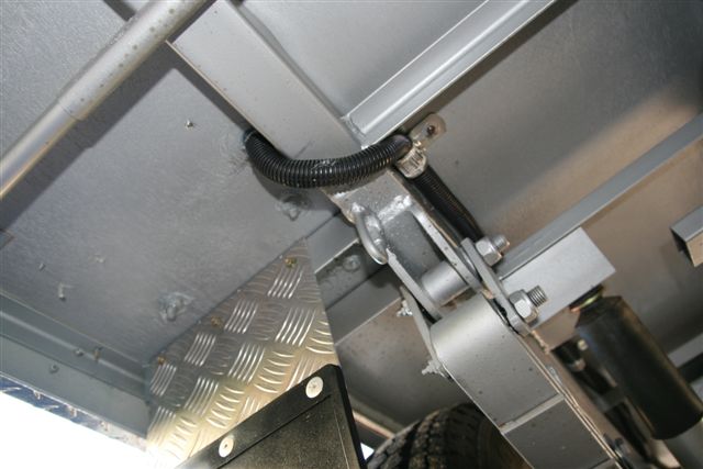
Cub drill holes in the ends of their draw bars for wiring
connections. The other side has the trailer plug wiring in it. Feed
both power cables into the draw bar until there is enough still
hanging out to reach your vehicle mounted Anderson plug, usually,
but not always, the same length as your trailer plug lead, and
secure with electrical tape so it stays at the right length. As the
cables poke out the other end of the draw bar they have to turned
back towards the tow hitch a short distance and fed into the main
lateral member of the chassis heading towards the rear of the
trailer. Where the cables are exposed here fit a short length of
split conduit and secure with a cable tie or two. When the cables
come out of the end of the lateral member they will be exposed to
stone damage so time to add some more split conduit. I secured the
conduit to the timber floor using single sided conduit saddles (3)
till I reached the point where the cable and conduit will enter the
interior via a hole you will drill, just a bit larger than the
conduit you have used, through the floor.
Use a small drill bit for a pilot hole as this will puncture
the vinyl flooring material inside and you can cut out a neat hole
with a Stanley knife for the cables to enter. It will also show you
if the two 6 B&S cables are going to come up in the right spot in
relation to the battery tray and the location of the charger. A
small pilot hole is much easier to hide than an 18 mm ooops ! If
your trailer chassis is the same as mine you will be very close to a
piece of steel angle, running across the chassis, as you bore
through the floor. Run the cables through the hole and push the
conduit 20mm or so into the hole as well. Seal around the conduit
with silicone sealant. If all has gone well you should have a meter
or so of cable coiled up under the bed next to the battery tray.
the
charger
This needs to be fitted in its final location now so you can
accurately measure the length to cut the cables. When cutting the
cables allow a bit extra, so should the need arise in the future, if
you change chargers, the terminals may be in a different location.
Fit lugs to ends of the cables by crimping or soldering. Crimpers
for a job like this will set you back anywhere from $40 to $100. I
had the equipment and knowhow to solder, so that is how I did it.
Whether crimping or soldering, fit the appropriate sized heat shrink
over the fitted lug(s) to support the connection. The heat shrink
should cover the round cable receptacle of the lug and at least 20
mm of the cable.
Place the new auxiliary battery in the tray and clamp it into
place.
Fit another pair of lugs to the leftover cables, these will
become the leads from the charger to the battery. Fit these cables
to the charger and run them to the correct terminals of the battery
and cut to length, allowing a bit extra for future changes. Fit
either lugs or terminals, whatever is appropriate for the type of
connections your new battery has, to the other end of these cables.
At this point your new auxiliary battery is able to be
charged from the tow vehicle. If it is not already installed a
circuit breaker should be fitted to the positive lead on the
charging cable of the tow vehicle as close to the auxiliary battery
or charging source on the tow vehicle as possible. This breaker
should be rated at 50 amps to match the rating of the Anderson plug.
A lower rating may be required depending on the input rating of your
chosen charger.
Now that we have all this power on hand it’s time to send it
out and do stuff !
the
control box
These can be as simple or as complicated as either your
ability, patience or wallet permit. There are a few ‘must haves’ to
call it a control box, switches and some fuses at least, as it’s job
is to send power out to the various power sockets, lights and other
appliances on your needs list. This brings us to the next step –
what are your needs ? I’m not going into power consumption
calculations relating to amp hours (battery capacity) but you will
need to know how much current (amps) your individual items draw when
running. This is to make sure that none of your electrical items
exceeds the rating of your control box components. This is unlikely
for the average camper. DC ‘camping’ fluro lights are generally
around an amp with LED’s about 200 mili/amps. An 80 litre Waeco with
a BD50 compressor will draw 7 amps for a couple of seconds when
starting up and then drop back to about a 5 amp draw when running.
My ARB fridge draws just 1.87 amps when running and about 4.2 amps
on start up, according to my multi meter. Working out what you want,
or need, will also help you with the number of switches and sockets
you need to purchase and ultimately how big your control box or
panel will need to be.
So, work out your needs, buy your components and then work
out how big a box or panel you will need.
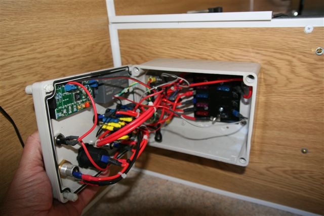
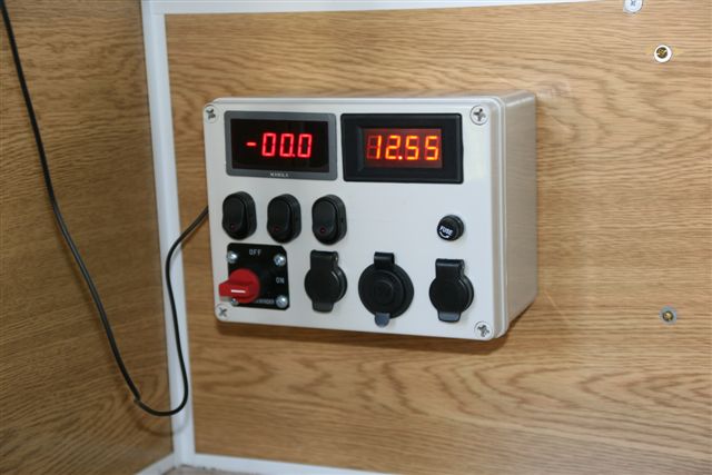
I built my control box to suit my requirements as well as
trying a few things because I could ! I have an amp meter to see
what I am using, a volt meter to see how my batteries are doing.
Rough rule of thumb, 12.8 v = full, 12.6 v = ½ full, 12.4 v = ¼
full, 12.0 v = flat. I did say rough ! Also four Narva 62059 BL
switches with red LED indicators, 1 x cigarette & 2 x merit sockets,
a panel mount 1 amp fuse for the volt meter display (you need to use
separate 12volt supplies for the digital displays otherwise your
volt meter may read low. Why, I have no idea !) and an isolation
switch to disconnect the batteries from everything else (except the
charger).
If the box building thing seems a bit too time consuming or
daunting ABR Sidewinder has an excellent ready made panel for about
$95 which can be surface mounted or is a perfect fit for the large
box he sells as well. Saves a lot of time and probably will be
sufficient for the average punter. Have a look at
http://www.sidewinder.com.au/page108.html
This panel could be surface mounted in the same location as I
have installed my control box, but would need a large hole to be cut
into the bulkhead which I just couldn’t bring myself to do.
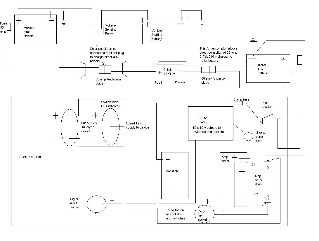
Whilst the internals of my box resembles a fist full of
spaghetti, it is a fairly straight forward wiring job if you follow
the diagram. This was my first go at using MS paint for a wiring
diagram so its pretty average.
This system has been installed now for a couple of months and
works well. The volt meter seems to be reading a little low, about
0.2 of a volt, and I’m not sure if it’s my wiring that is at fault
or if it’s that the meter only cost me $22 on Ebay !
If there is a down side I can find at this stage it is that
the auxiliary battery in my truck powers the Ctek 12 volt/12 volt
charger in the trailer. If the charging of the trailer battery(s)
doesn’t reach the ‘float’ stage i.e. fully charged, then you can be
left with a partially charged truck auxiliary battery if it hasn’t
had sufficient time to fully charge. This happened recently when we
re-located from the Callala Beach weekend to Greenwell Point for an
‘extended’ break.
This is only a 20 minute drive and because I had been running
my fridge from the trailer battery for four days it was fairly low.
I had moved the fridge to its usual travel place in the truck and
plugged it in for the short drive and it fired up ok. I connected up
the charging plug for the trailer at the hitch which started up the
charger in the trailer and away we went. After arriving at our next
stop I switched the truck off and after about 10 minutes noticed the
fault light on the fridge flashing. I checked and found that it had
stopped altogether ! A quick move inside and connection to mains
power and all was good with the fridge, must be a problem with the
truck. With the trailer (and charger) still connected I put a multi
meter onto the truck auxiliary battery – 10.6 volts ! Not so good. I
disconnected the trailer charger and it rose to about 11.5 volts.
The combination of powering the fridge and the trailer charger and
the short run had left me with an all but flat auxiliary battery.
Apart from avoiding this scenario in the future I’m open to
suggestions for a remedy to this one.
thanks to Gary
Laker for sharing this idea
november 2010
|